Adding a Laser to Your Shapokeo on the Cheap
- RustyRaptor
- Mar 14, 2020
- 8 min read
Updated: Sep 16, 2021
Written by Kurt Greenwald, adapted by The Rusty Raptor
So when adding a laser attachment to your Shapokeo machine you have a few options shell out $750 or you can go the easy DIY route and SAVE A TON! You can add a laser to your set up for under $175 and take your building to a new level. Taking on a project like this can seem daunting, but Let's check out this super easy walkthrough by our friend Kurt Greenwald.
Parts You Need:
-Laser Bundle- https://amzn.to/3b14Mq5 (Comes with Laser Module, Driver Board, 12v Power Supply and Cord, Hook Up Wires, Laser Safety Glasses

(Website states laser is for the “Genmitsu CNC” machine that they also offer on Amazon. But this will work just fine on our Shapeoko.)
ADA Fruit Break Away Pins- https://www.adafruit.com/product/3662?gclid=Cj0KCQiApt_xBRDxARIsAAMUMu8EWWTjnYQe 2fEsS7R15KOKwIM01AEgb7q2EfuvH7WI42v53WrVNRsaAn1vEALw_wcB
PRE-MADE WIRE HARNESS AND PARTS FOR SHAPEOKO- https://store16954098.ecwid.com/products/198134794
LET'S BUILD IT!
Mounting the laser diode to your Shapeoko:
“There are 1000 ways to skin a cat”. I wanted to find a way to keep this modular. I didn't want extra parts hanging off my machine when I'm working on projects that don't include laser etching.
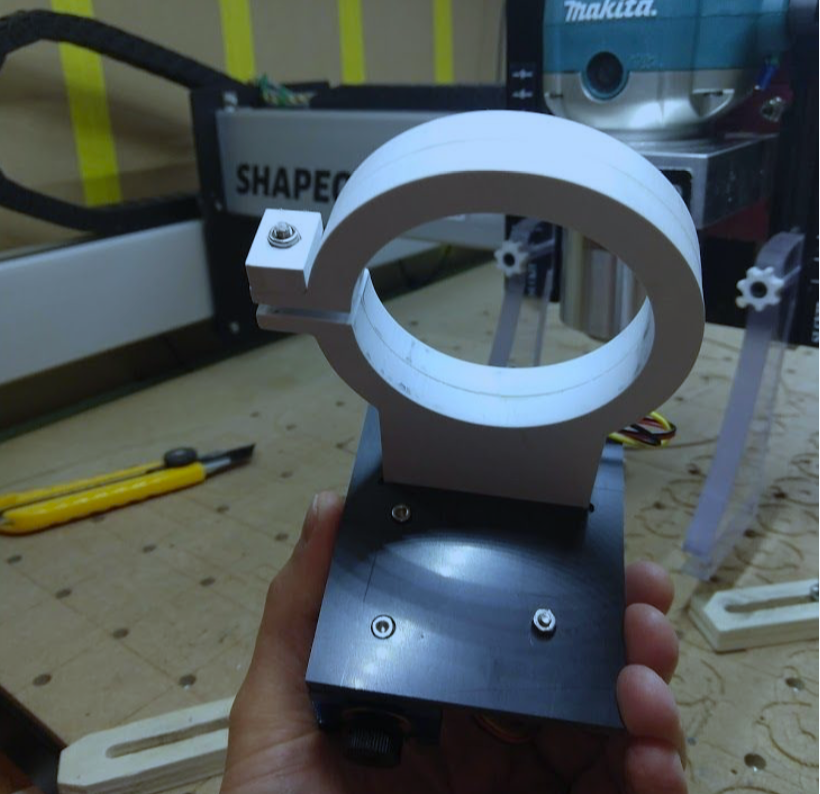
I also didn’t want the driver module exposed to the dusty environment of my CNC enclosure when not in use. (especially since the driver that came with my unit has a cooling fan)My chosen solution was a mounting system that can be removed easily and set aside when doing the normal dusty/dirty millwork in wood, plastics and metals. I happened to have enough scraps of some white and gray acrylic in my stash, so that's what I used. It's really nothing more than a plastic band clamp that you can slip up onto the base of the router and cinch down tight with a nut and bolt.
Kinda like some of the router mounted dust boots we use on our CNC machines. This type of mount could easily be fabricated with plywood or other materials, but I work a lot with plastics and had enough of these materials on hand to make something work.(Search the forums and FB user page for additional examples of CNC made or 3D printed Shapeoko laser mounts) I'm not going to go into detail here since mine is a hodgepodge mount made from whatever I had lying around. In the end most of us already have a CNC machine that makes fabricating something like this a fairly simple task. So put your thinking cap on, take some measurements and put the Shapeoko to use in making a mount that suits you.
YOU CAN ALSO VISIT www.THERUSTYRAPTOR.com store for pre-made mounting options
Shapeoko board PWM output connection to the input connection on the laser driver board:
The connection points are really simple. You don't need to be some sort of electronics wiz for any of this. You'll have to take the black metal box cover off of your Shapeoko board and locate the PWM (pulse width modulation) & GND (ground) connections. Note: there are different versions of the Carbide board depending on when your machine was manufactured/purchased. So the location of the PWM & GND connection points we are looking for may vary. On my version 2.4 board they are located in the upper right hand corner. They are labeled on the board, but the text is super tiny. So put your glasses on or dig out a magnifying glass to get a good look at it.

You may have noticed in the photo above that there is no socket or pin headers on the C3D board's PWM & GND connection points. It certainly would have made things a lot easier if there were, so we'll have to find a solution to that. I do some hobbyist electronics work so I figured it would be very simple to just unmount the board, throw it up on my work-table, grab some pin headers out of my electronics bin and solder them on. If you've ever muddled around with
soldering components to a thru-hole PCB (printed circuit board) you'd know that soldering is typically done from the backside of the board. The process is usually, grab a strip of breakaway pin headers, break off a section with the number of pins needed, slip the ends to be soldered through the holes on the surface of the board, flip it over and make your solder joint on the rear. Well it would seem that in addition to the 4 hex screws, there is also a heat sink paste holding the C3D board to the aluminum heat sink block. I was reluctant to try and pry it free and risk damaging the board. I also didn't feel like cleaning up that goo and having to buy more heat sink paste. I was also weary about trying to solder to the front face of the board, so I went searching for a solution. Most of us are probably familiar with the popular J-Tech laser kit that sells for upwards of $700. YIKES!! Anyway, their kits include some solderless pin headers for ease of installation. That appears to be a reasonable solution so I went searching for a source for just such a thing

ADA Fruit Break Away Pins- https://www.adafruit.com/product/3662?gclid=Cj0KCQiApt_xBRDxARIsAAMUMu8EWWTjnYQe 2fEsS7R15KOKwIM01AEgb7q2EfuvH7WI42v53WrVNRsaAn1vEALw_wcB
Once you have the solderless pin header strip in hand, simply break off a 2 pin section. Something like a small pair of pliers may make it easier to break off a section. Adafruit has a video on actually installing this entire strip to a Raspberry Pie board by use of a hammer. I don't think we need to go to that extreme for just 2 pins.... But take care when inserting and pushing these into your C3D board. You alone are responsible if you break your board trying to push these solderless pins in place. I took another piece of scrap plastic, drilled some small holes in it and used that to put uniform pressure on the plastic base of the 2 pin section while pushing into place.


Okay, now that your C3D board is prepared we can turn our attention to the wires themselves. Again, this is very simple. The PWM pin on the C3D board needs to connect to the PWM pin on your laser driver board, and the GND pin on the C3D board needs to connect to the GND pin on the laser driver board. 2 wires...That's it!!! The laser driver board you purchase may or may not come with some documentation to make identifying the pin-outs easier. The one I bought does have some small labeled text on the board itself, but it's difficult to see and doesn't show which pin is the PWM and which is the GND. The kit was packaged with a CD rom with some .pdf documentation on board. Luckily there was a reference diagram. That 3 pin connection point to the right of the 2 pin is for connection to the SainSmart CNC machine that I mentioned earlier. We won't be using anything from that 3 pin port for our Shapeoko connection. So they can just be ignored for the purposes of a Shapeoko installation. The driver board that came with this kit has a standard 5.5mm power jack. And since it came equipped with its own power supply it’s just as simple as plugging one end into the wall socket and the other into the laser driver board. The laser to driver board to the actual laser connections are color coded and self explanatory (one is the laser itself and the other for the cooling fan).

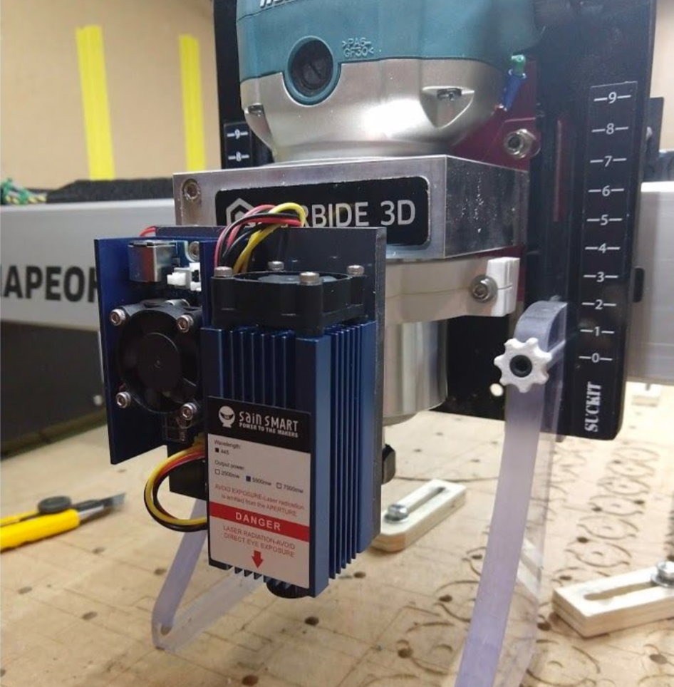
Routing the wires is up to you. Obviously you won’t want them hanging loose where they can get tangled up in the moving parts of the Shapeoko, or get in the way of a hot burning laser beam. I chose to route them neatly up through my drag chains. You could just as easily zip tie them to the outside of the drag chains if you so please. I took some 22 awg black and red wires and created a paired twist using a power drill.
Here is a video example: https://www.youtube.com/watch?time_continue=75&v=uTJhrTTl-EE&feature=emb_logo
Wire twisting is not really a necessity. You could just leave the wires separated/un-twisted, or even source a jacketed pair of wires. Whatever you do, just ensure you start with a longer length of wire than you think you’ll need. Extra can be trimmed off later.I started by soldering on a JST connector on the Shapeoko control box end, plugged that in to the press fit pin header we already installed, then worked the twisted wire pair up through the drag chains. Basically I’m following the Yellow & Black twisted wire pair that leads up to the Z limit switch with my new Red & Black pair for the laser. (I’d recommend having some zip ties handy to keep things tidy)

Now that the wires are routed, you can either choose to simply solder on another JST connector to interface socket on the laser driver board, or do something like I did. I had some of these barrel plugs on hand from another project. I’m using this for my connect/disconnect point instead of relying on the very small and fragile JST connection on the board.Here is a photo of the business end all connected up. The left barrel connector is the PWN/GND connection coming from the Shapeoko board and the right is the kit supplied 12v power supply. When I’m not using the laser, I’ll just unplug these and tie them up out of the way near my Z stepper motor. You may notice that I did not route the power supply cord through my drag chains. Reason being, the kit supplied power supply cord is not long enough. I may go back and extend the cord at some point, but for now I’m just going to leave it external and be careful to keep it free and clear from moving parts and lasers.

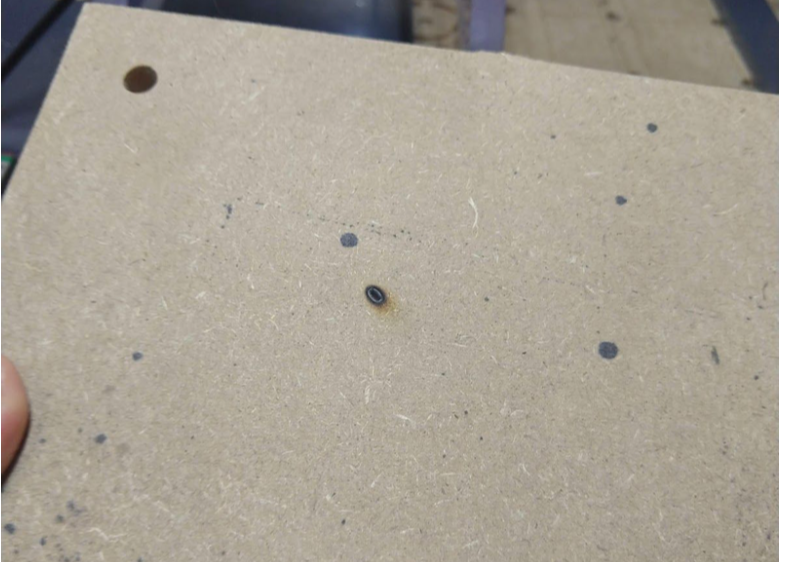
I donned the safety glasses and powered on the laser by itself to ensure it turns on. Success! It burns stuff!!! (the shapeoko is not powered or otherwise connected to my pc at this point)

Keep your power on test to a minimum. I put a piece of scrap MDF under the laser to keep it from burning directly on my wasteboard. But beware....you could very easily start a fire here with the laser being stationary. In this power on test the laser is firing at full power. Once you have software control over the laser, power can be dialed down as not to burn anything while establishing your XYZ zero points.
Now on to attempting control of this thing with the Shapeoko. Lightburn software seems to be the overwhelming consensus for the laser burning compatibility using the Shapeoko and Carbide Motion. They have a free trial you can download to play around with. When the trial period expires it’s about $40 per year for a
I’m not going to go into detail here because this process is already documented very well in Ben Myers youtube video (see link below). Please watch his video in its entirety. He explains how to control the project setup functions you’d normally do within Carbide Motion with the Lightburn software (jogging, setting your XYZ zero points, etc). He also explains how to toggle back to CNC mode when you're done with your laser project. In a nutshell, you have to change some of the Shapeoko GRBL settings to be compatible with the Lightburn software, then change them back when you want to go back to normal CNC operations. It’s a simple process once you get your head wrapped around it. If you ignore these instructions you’ll probably find yourself very frustrated. So again. WATCH THE WHOLE VIDEO!!!
That’s about it. This thing can create frickin fire with frickin la-zer beams, so have fun, but most importantly, BE SAFE!!!


Comments